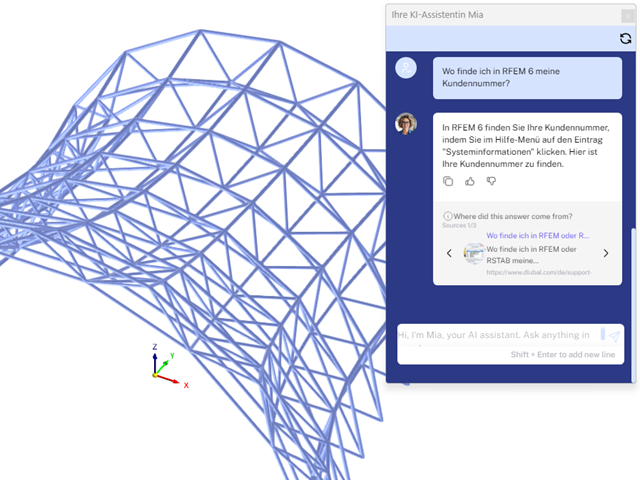
Mia is accessible in the programs and prevents the hassle of following up by email or phone.

The modal relevance factor (MRF) can help you to assess to which extent specific elements participate in a specific mode shape. The calculation is based on the relative elastic deformation energy of each individual member.
The MRF can be used to distinguish between local and global mode shapes. If multiple individual members show significant MRF (for example, > 20%), the instability of the entire structure or a substructure is very likely. On the other hand, if the sum of all MRFs for an eigenmode is around 100%, a local stability phenomenon (for example, buckling of a single bar) can be expected.
Furthermore, the MRF can be used to determine critical loads and equivalent buckling lengths of certain members (for example, for stability design). Mode shapes for which a specific member has small MRF values (for example, < 20%) can be neglected in this context.
The MRF is displayed by mode shape in the result table under Stability Analysis → Results by Members → Effective Lengths and Critical Loads.

The "Spring" member type is used to simulate linear and nonlinear spring properties via a linear object. This input function helps you to model the stiffness specifications in the force/displacement unit.
Go to Explanatory Video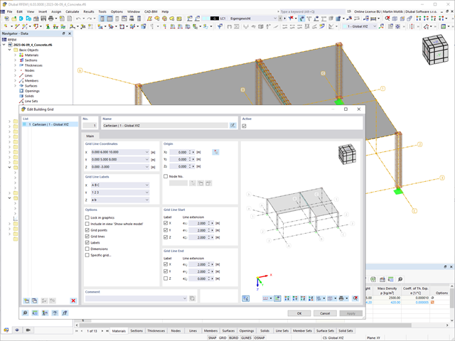
The "Building Grid" guide object supports you in the design of your structure. It features intuitive grid coordinate input and grid line labeling.
You can quickly place grids in space and label them by specifying a graded coordinate code. The grid line end modification allows you to optimize the grid appearance. Furthermore, a preview helps you to define the building grid.
Go to Explanatory Video
Would you like to perform cross-section design checks for cold-formed steel members according to EN 1993‑1‑3? No matter if you design the cold-formed sections from the cross-section library or the general cold-formed (non-perforated) sections from RSECTION – your structural analysis program helps you to determine the effective cross-section, taking into account the local buckling and instability. You can also perform a cross-section check according to EN 1993‑1‑3, 6.1.6. In this case, the internal forces from the calculation using Torsional Warping (7 DOF) are taken into account by means of the equivalent stress check
Go to Explanatory Video
Do you already know the editor for mesh refinement control? It is a great help for your work! Why? It's easy – it gives you the following options:
- Graphic visualization of the areas with mesh refinements
- Mesh refinement of zones
- Deactivating the standard 3D solid mesh refinement with transversion into the corresponding manual 3D mesh refinements.
These options help you to formulate a suitable rule for meshing the entire model, even for the models with unusual dimensions. Use the editor to efficiently define small model details on large buildings or detailed meshing areas in the coating area of the model. You will be amazed!

Can you use some support? The "surface model" member type helps you to simulate a member as a surface model in the overall model.
This feature provides you with the following:
- Quick input using a member with a cross-section
- Simulation of openings in the web
- Simultaneous output of the member and surface results
- Design of member results in the add-on
- Consideration of a real stress distribution
You can use the surface member for the following applications, among others:
- Castellated beams
- Perforated beams
- Beams with rectangular openings
- Vierendeel trusses
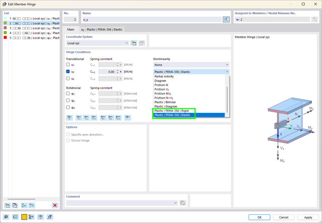
What are plastic hinges? Very simple – plastic hinges according to FEMA 356 help you to create pushover curves. These are nonlinear hinges with preset yield properties and acceptance criteria for steel members (Chapter 5 of FEMA 356).

In the case of rectangular cross-sections, you can usually achieve a direct connection by using welds. However, you can also connect them to other cross-sections in the same way. Furthermore, other components such as end plates help you to connect the rectangular cross-sections to other structural components.
.png?mw=640&hash=55038d2a1591f62179796666cb9b2fede0274e19)
A graphical and tabular output of the results for deformations, stresses, and strains helps you when determining the soil solids. To achieve this, use the special filter criteria for targeted selection of results.
The program doesn't leave you alone with the results. If you want to graphically evaluate the results in the soil solids, you can use the guide objects. For example, you can define clipping planes. This allows you to view the corresponding results in any plane of the soil solid.
And not just that. The utilization of result sections and clipping boxes facilitates the precise graphical analysis of the soil solid.

The Steel Design add-on helps you, among other things, to design general cross-sections that are not predefined in the cross-section library. To do this, create a cross-section in the RSECTION program and then import it into RFEM/RSTAB. Depending on the design standard that you have used, you can select from various design formats. One of them is, for example, the equivalent stress analysis. Do you have a license for RSECTION and Effective Cross-Sections? Then you can also perform the design checks that take into account the effective cross-section properties according to EN 1993‑1‑5.
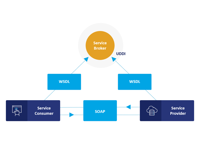
Communication is the key to success. This also applies to a client-server relation. WebService and API provides you with an XML based information exchange system for direct client-server communication. Programs, objects, messages, or documents can be integrated into these systems. For example, a web service protocol of the HTTP type runs for the client-server communication when you are looking for something in the Internet using a search engine.
Now back to Dlubal Software. In our case, the client is your programming environment (.NET, Python, JavaScript) and the service provider is RFEM 6. Client-server communication allows you to send requests to and receive feedback from RFEM, RSTAB, or RSECTION.
What is the difference between WebService and an API?
- WebService is a collection of open source protocols and standards used to exchange data between systems and applications. In contrast, an application programming interface (API), is a software interface through which two applications can interact without a user being involved.
- Thus, all web services are APIs, but not all APIs are web services.
What are the advantages of the WebService technology?
You can communicate more quickly within and between organizations.A service can be independent of other services.Webservice allows you to use your application to make your message or feature available to the rest of the world.Webservice helps you to exchange data between different applications and platforms Several applications can communicate, exchange data, and share services with each other. SOAP ensures that programs created on different platforms and based on different programming languages can exchange data securely.
Communication between the web service client and server is optionally encrypted via the https protocol. To do this, you can install an SSL certificate with the corresponding private key in the settings.
Do you already know about RSECTION 1? The stand-alone program RSECTION helps you to determine the section properties for any thin-walled and massive cross-sections. Then, it performs a stress analysis. RSECTION combines the programs SHAPE‑THIN and SHAPE‑MASSIVE. Compared to these programs, we have added the following new features in RSECTION:
- Graphical display of stress components
- Scripting using Javascript

By solving the numerical flow problem, you can obtain the following results on and around the model:
- Pressure on structure surface
- Coefficient Cp distribution on the structure surfaces
- Pressure field about the structure geometry
- Velocity field about the structure geometry
- Turbulence k-ω field about the structure geometry
- Turbulence k-ε field about the structure geometry
- Velocity vectors about the structure geometry
- Streamlines about the structure geometry
- Forces on member-shaped structures that were originally generated from member elements
- Convergence diagram
- Direction and size of the flow resistance of the defined structures
Despite this amount of information, RWIND 2 remains clearly arranged, as is typical for the Dlubal programs. You can specify freely definable zones for a graphic evaluation. Voluminously displayed flow results about the structure geometry are often confusing – you know the problem for sure. That's why RWIND Basic provides freely movable section planes for the separate display of the "solid results" in a plane. For the 3D branched streamline result, you have an option to select between a static and an animated display in the form of moving line segments or particles. This option helps you to represent the wind flow as a dynamic effect.
You can export all results as a picture or, especially for the animated results, as a video.
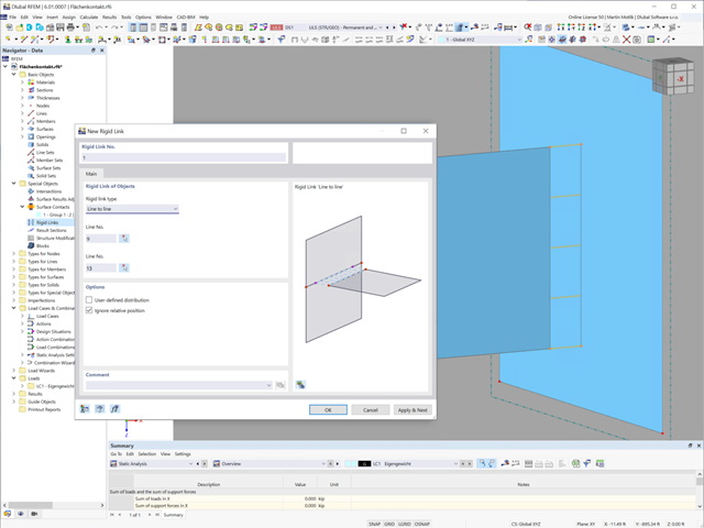
This feature helps you with links. You can easily define rigid links between two lines or surface edges.
Go to Explanatory Video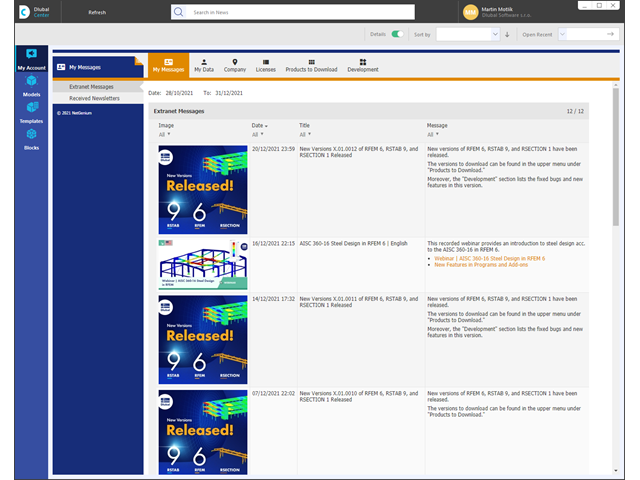
Take a look at the "My Account" category. This is where your customer data, such as address, licensed programs, and add-ons are managed. It also takes you straight to the Dlubal website. Find out about the latest news there, use online services such as "Snow Load Zones, Wind Zones and Earthquake Zones", or get helpful information from the FAQ database.
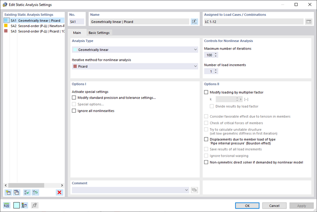
This feature helps you with the load application. You can have the required loading applied incrementally. This option is particularly suitable for your calculations according to the large deformation analysis. Furthermore, you can easily perform post‑critical analyses in RFEM.
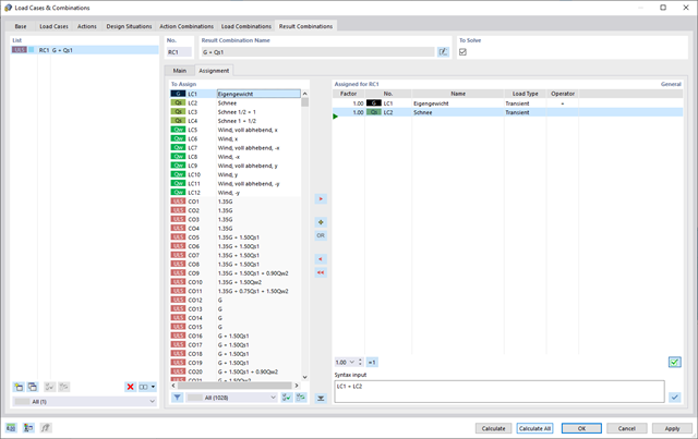
RFEM 6 offers you a wide range of helpful and efficient functions for working with load combinations. You can add the load cases included in load combinations together and then calculate them in consideration of the corresponding factors (partial safety and combination factors, coefficients regarding consequence classes, and so on). Generate the load combinations automatically in compliance with the combination expressions of the standard. You can perform the calculation according to the linear static analysis, second-order analysis, or large deformation analysis, as well as for post-critical analysis. Optionally, you can define whether the internal forces should be related to the deformed or non-deformed structure.
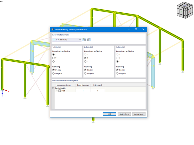
This feature helps you stay flexible in your planning. You can subsequently adjust the numbering of structural objects, such as nodes and members. In this case, it is possible to renumber the objects automatically in accordance with the selected priorities (axis directions).
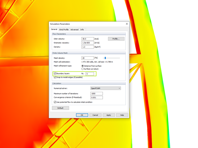
The meshing algorithm of RWIND Simulation uses the boundary layer option to mesh the area near the model surface with a voluminous layer mesh. The number of layers is controlled by a user-defined parameter.
This fine mesh in the area of the model surface helps to represent the wind velocity close to the surface.
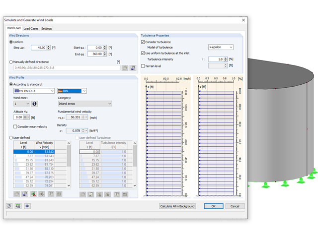
Rely on the Dlubal programs even in windy matters. RFEM and RSTAB provide a special interface for exporting models (that is, structures defined by members and surfaces) to RWIND 2. There, the wind directions to be analyzed for your project are defined by means of related angular positions about the vertical model axis. Furthermore, the elevation-dependent wind profile and turbulence intensity profile are defined on the basis of a wind standard. These specifications result in specific load cases, depending on the angle. For this, the fluid parameters, turbulence model properties, and iteration parameters that are all stored globally are helpful. You can extend these load cases by partial editing in the RWIND 2 environment using terrain or environment models from STL vector graphics.
As an alternative, you can also run RWIND 2 manually and without the interface application in RFEM or RSTAB. In this case, the structures and terrain environment in the program are directly modeled by imported STL and VTP files. You can define the height-dependent wind load and other fluid-mechanical data directly in RWIND 2.
Due to its versatile applicability, RWIND 2 is always at your side to support you in your individual projects.
Always keep an eye on your results. In addition to the resulting load cases in RFEM or RSTAB (see below), the results from the aerodynamics analysis in RWIND 2 represent the flow problem as a whole:
- Pressure on structure surface
- Pressure field about structure geometry
- Velocity field about structure geometry
- Velocity vectors about structure geometry
- Flow lines about structure geometry
- Forces on member-shaped structures that were originally generated from member elements
- Convergence diagram
- Direction and size of the flow resistance of the defined structures
These results are displayed in the RWIND 2 environment and evaluated graphically. The flow results around the structure geometry in the overall display are rather confusing, but the program has a solution for this. In order to present clearly arranged results, freely movable section planes are displayed for the separate display of the 'solid results' in a plane. Accordingly, for the 3D branched streamline result, the program presents you an animated display in the form of moving lines or particles in addition to the static one. This option helps to represent the wind flow as a dynamic effect.
You can export all results as a picture or, especially for the animated results, as a video.
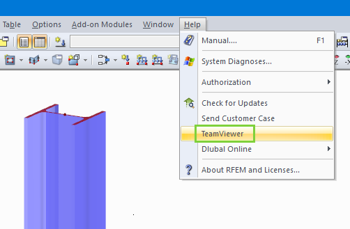
It is possible to access the TeamViewer directly by opening the Help menu of RFEM and RSTAB. Customers with Service Contract Pro can thus benefit from easy and quick online support via video conference.

The introductory examples and tutorials for RFEM 5 and RSTAB 8 will help you to get started with the program. Step by step, you will become familiar with the most important features. You can download the documents in PDF format.
Introductory Example for RFEM 5 (PDF) Tutorial for RFEM 5 (PDF) Introductory Example for RSTAB 8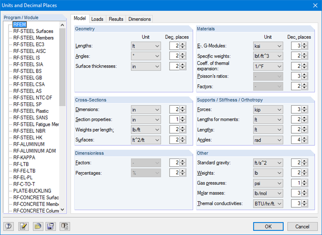
A global dialog box manages the units of input data, loads, and results in RFEM/RSTAB as well as in all add‑on modules.
Take advantage of the helpful functions offered below: You can save your settings and import them again later. In this way, you can This requires, for example, to use different sections for steel and reinforced concrete structures.
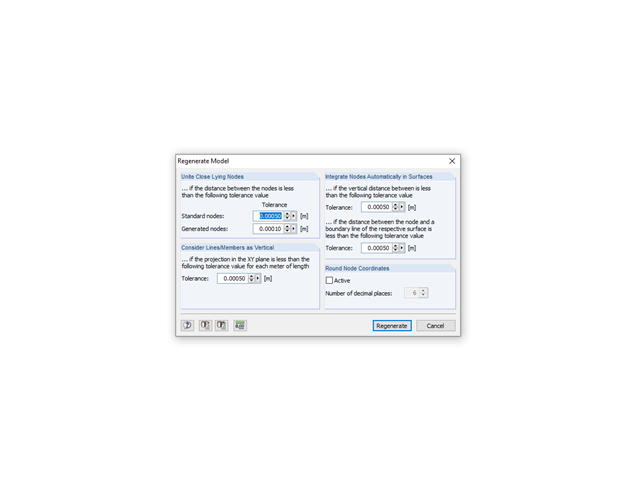
It is possible to edit a model in the active rendering. The 'Regenerate Model' function may help you to correct slight deviations of node coordinates.
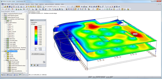
After the calculation, the module shows clearly arranged tables listing the results of the nonlinear calculation. All intermediate values are included in a comprehensible manner. Graphical representation of design ratios, deformations, concrete and reinforcing steel stresses, crack widths, crack depths, and crack spacing in RFEM facilitates a quick overview of critical or cracked areas.
Error messages or remarks concerning the calculation help you find design problems. Since the design results are displayed by surface or by point including all intermediate results, you can retrace all details of the calculation.
Due to the optional export of input or result tables to MS Excel, the data remain available for further use in other programs. The complete integration of results in the RFEM printout report guarantees verifiable structural design.